

Item description
| Information |
Item weight
Barcode
Created time
Last updated on
|
| Item description |
With high-current relays, AC250V 10A ; DC30V 10A NOTE: Each relay draws about .08A (80ma) so about 4 relays are the maximum you should run from the Arduino +5V supply. (Running from USB it may be less). More than 2 relays: we recommend you use a separate 5V supply for the relays.
Dimensions here: http://arduino-info.wikispaces.com/RelayDimensions
NOTES: If you want complete optical isolation, connect "Vcc" to Arduino +5 volts but do NOT connect Arduino Ground. Remove the Vcc to JD-Vcc jumper. Connect a separate +5 supply to "JD-Vcc" and board Gnd. This will supply power to the transistor drivers and relay coils.
If relay isolation is enough for your application, connect Arduino +5 and Gnd, and leave Vcc to JD-Vcc jumper in place.
NOTE: It is sometimes possible to use these relay boards with 3.3V signals, IF the JD-VCC(RelayPower) is provided from a +5V supply and the VCC to JD-VCC jumper is removed. . That 5V relay supply could be totally isolated from the 3.3V device, or have a common ground IF opto-isolation is not needed. If used with isolated 3.3V signals, VCC (To the input of the opto-isolator, next to the IN pins) should be connected to the 3.3V device's +3.3V supply. NOTE: Some RaspberryPi users have found that some relays are reliable and others do not actuate sometimes. It may be necessary to change the value of R1 from 1000 ohms to something like 220 ohms, or supply +5V to the VCC connection.
NOTE: The digital inputs from Arduino are Active LOW: The relay actuates and an LED lights whe the input pin is LOW, and turns off on HIGH. See the Wiki article for how-to assure relays do not activate at power-on time.
Schematic Diagram: 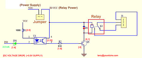   |
| Conditions |
|
| Tags |
Exchange or return policy
Every item comes with a 30-day warranty. However, there are certain conditions that apply:
-
The customer should not be responsible for any self-inflicted damage, such as incorrect power connections (for example, supplying 5V instead of the required 3.3V for a sensor).
-
The product must be in perfect condition, without any breakage or damage caused by electricity (e.g., short circuits leading to electrical fires).
-
The store does not accept product exchanges due to customer misunderstandings, such as purchasing the wrong size for their project or buying something without eventually using it. Customers can inquire about the product details and ensure compatibility before making a purchase by contacting us through our Line account @modulemore during business hours. Please note that there may be delays in response between 12:00 PM and 2:00 PM.
Return Policy: To initiate a product return, customers must provide the original receipt or a copy for quick verification. Returns can be sent to our store address by following these guidelines:
- Provide a detailed description of the damaged item(s).
- Mention any tests or experiments conducted by the customer.
Please note that the store reserves the right to make the final decision regarding product replacement or refund.
English▾


MEMBER ZONE

JOIN US
ร้านModuleMore
/www.modulemore.com/en
Become a member of this store to receive special offers and promotions
 ModuleMore
Become a member of this store to receive special offers and promotions


Special thanks very good images from Freepik
English▾
Choose your language
Language
Currency
Change
Modify language
▲
▼
My orders
My orders
This seller's information

ModuleMore
Arduino compatible board, Iot, ESP32, ESP8266, Nodemcu, Raspberry pi, micro:bit and etc.
Mobile number : 0831710868
E-mail : paheyisoicus@gmail.com
E-mail : paheyisoicus@gmail.com
Send message to seller
About this seller
Search items from this seller
Search for items
Recently viewed items
Favourite this seller
Join as a Member
Share this page
Share this page
↑
TOP Back to top
TOP Back to top
Items in cart ({{total_num}} type)

We apologise, your cart currently is empty
Total
฿ {{price_format(total_price)}}
- ฿ {{price_format(discount.price)}}
Total
{{total_quantity}} Unit(s)
฿ {{price_format(after_product_price)}}
excluding shipping fee
VAT Included.
➜ Continue shopping