

รายละเอียดสินค้า
| ข้อมูล |
น้ำหนัก
บาร์โค้ด
ลงสินค้า
อัพเดทล่าสุด
|
| รายละเอียดสินค้า |
With high-current relays, AC250V 10A ; DC30V 10A NOTE: Each relay draws about .08A (80ma) so about 4 relays are the maximum you should run from the Arduino +5V supply. (Running from USB it may be less). More than 2 relays: we recommend you use a separate 5V supply for the relays.
Dimensions here: http://arduino-info.wikispaces.com/RelayDimensions
NOTES: If you want complete optical isolation, connect "Vcc" to Arduino +5 volts but do NOT connect Arduino Ground. Remove the Vcc to JD-Vcc jumper. Connect a separate +5 supply to "JD-Vcc" and board Gnd. This will supply power to the transistor drivers and relay coils.
If relay isolation is enough for your application, connect Arduino +5 and Gnd, and leave Vcc to JD-Vcc jumper in place.
NOTE: It is sometimes possible to use these relay boards with 3.3V signals, IF the JD-VCC(RelayPower) is provided from a +5V supply and the VCC to JD-VCC jumper is removed. . That 5V relay supply could be totally isolated from the 3.3V device, or have a common ground IF opto-isolation is not needed. If used with isolated 3.3V signals, VCC (To the input of the opto-isolator, next to the IN pins) should be connected to the 3.3V device's +3.3V supply. NOTE: Some RaspberryPi users have found that some relays are reliable and others do not actuate sometimes. It may be necessary to change the value of R1 from 1000 ohms to something like 220 ohms, or supply +5V to the VCC connection.
NOTE: The digital inputs from Arduino are Active LOW: The relay actuates and an LED lights whe the input pin is LOW, and turns off on HIGH. See the Wiki article for how-to assure relays do not activate at power-on time.
Schematic Diagram: 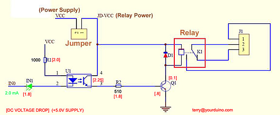 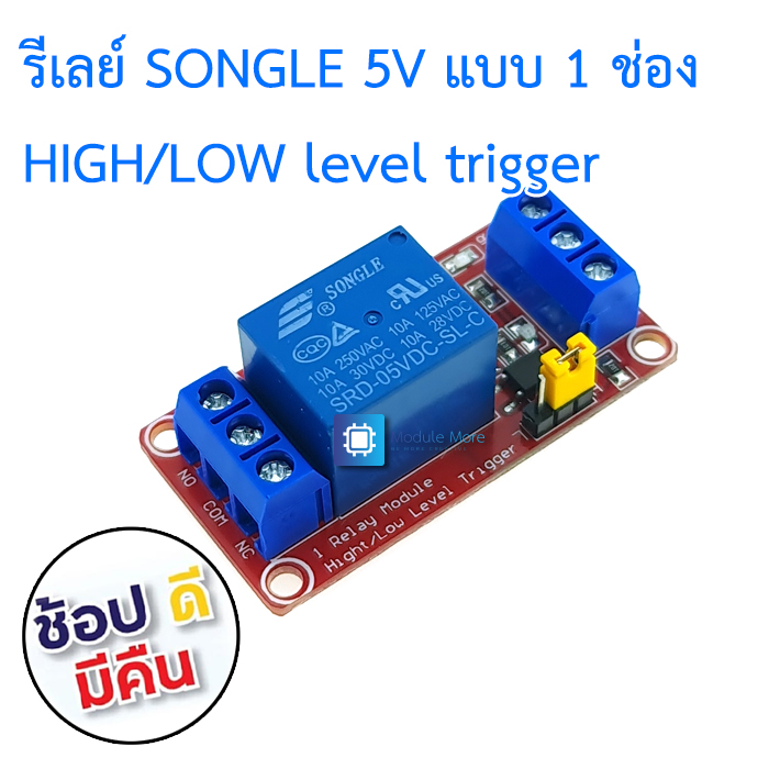 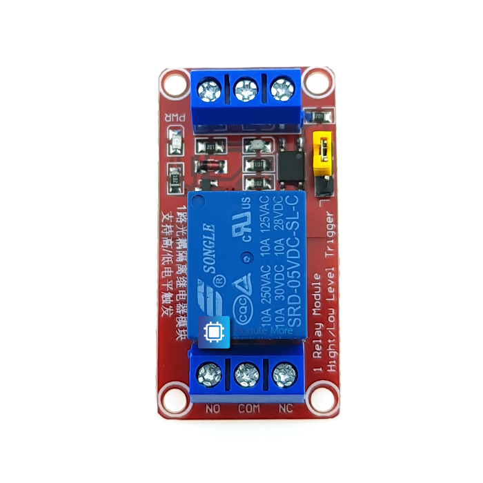 |
| เงื่อนไขอื่นๆ |
|
| Tags |
นโยบายการเปลี่ยนหรือคืนสินค้า
สินค้าทุกชิ้นมีการรับประกัน 30 วันครับ
โดยมีเงื่อนไขต่างๆดังนี้
1. ลูกค้าไม่ได้เป็นผู้ทำเสียหายเอง อาธิเช่น การต่อไฟเลี้ยงไม่ถูกต้อง (เซนเซอร์รับ 3.3v เราใส่ 5v อันนี้ไม่ได้เนอะ)
2. สินค้าต้องอยู่ในสภาพสมบูรณ์ ไม่แตกหักหรือเสียหายจากไฟ (เช่นไฟฟ้าลัดวงจรจนไฟไหม้)
3. ทางร้านไม่รับเปลี่ยนสินค้าจากความเข้าใจผิดของลูกค้าเอง เช่น ขนาดไม่ตรงกับงานที่ใช้, หรือซื้อไว้แต่ไม่ได้ใช้งาน เป็นต้น ลูกค้าสามารถสอบถามข้อมูลสินค้าหากมีความคลุมเครือก่อนสั่งซื้อได้ในไลน์ร้าน @modulemore ตลอดวันทำการ ยกเว้นเวลา 12.00-14.00 ที่อาจมีการตอบช้าในช่วงนี้
การส่งคืนสินค้า
การส่งคืนสินค้าจำเป็น ต้องมีใบเสร็จหรือสำเนา เพื่อความรวดเร็วในการตรวจสอบครับ
สามารถส่งคืนได้ผ่านที่อยู่ของร้าน คลิ๊ก โดยเขียนเป็นลายลักษณ์อักษรกำกับดังนี้
1. รายละเอียดรายการเสียหาย
2. ลูกค้าได้ทดสอบอะไรไปบ้าง
ทางร้านขอสงวนสิทธิ์ในการตัดสินใจเปลี่ยนสินค้าหรือคืนเงินครับ
ไทย▾


MEMBER ZONE

JOIN US
ร้านโมดูลมอร์
/www.modulemore.com/
สมัครสมาชิกร้านนี้ เพื่อรับสิทธิพิเศษ


Special thanks very good images from Freepik
ไทย▾
Choose your language
Language
Currency
Change
เปลี่ยนภาษา
▲
▼
รายการสั่งซื้อของฉัน
รายการสั่งซื้อของฉัน
ข้อมูลร้านค้านี้

โมดูลมอร์
ขาย arduino, diy, เรียน arduino, ทำหุ่นยนต์, ฝึกเขียนโปรแกรม, ตั้งแต่ระดับเริ่มต้นจนชำนาญ
เบอร์โทร : 0831710868
อีเมล : modulemore@gmail.com
อีเมล : modulemore@gmail.com
ส่งข้อความติดต่อร้าน
เกี่ยวกับร้านค้านี้
ค้นหาสินค้าในร้านนี้
ค้นหาสินค้า
สินค้าที่ดูล่าสุด
บันทึกเป็นร้านโปรด
Join เป็นสมาชิกร้าน
แชร์หน้านี้
แชร์หน้านี้
↑
TOP เลื่อนขึ้นบนสุด
TOP เลื่อนขึ้นบนสุด
สินค้าในตะกร้า ({{total_num}} รายการ)

ขออภัย ขณะนี้ยังไม่มีสินค้าในตะกร้า
ราคาสินค้าทั้งหมด
฿ {{price_format(total_price)}}
- ฿ {{price_format(discount.price)}}
ราคาสินค้าทั้งหมด
{{total_quantity}} ชิ้น
฿ {{price_format(after_product_price)}}
ราคาไม่รวมค่าจัดส่ง
รวมภาษีมูลค่าเพิ่มแล้ว
➜ เลือกซื้อสินค้าเพิ่ม