

รายละเอียดสินค้า
| ข้อมูล |
น้ำหนัก
บาร์โค้ด
ลงสินค้า
อัพเดทล่าสุด
|
| รายละเอียดสินค้า |
Introduction to synchronous rectification technology: Parameter description: Output current adjustment method: 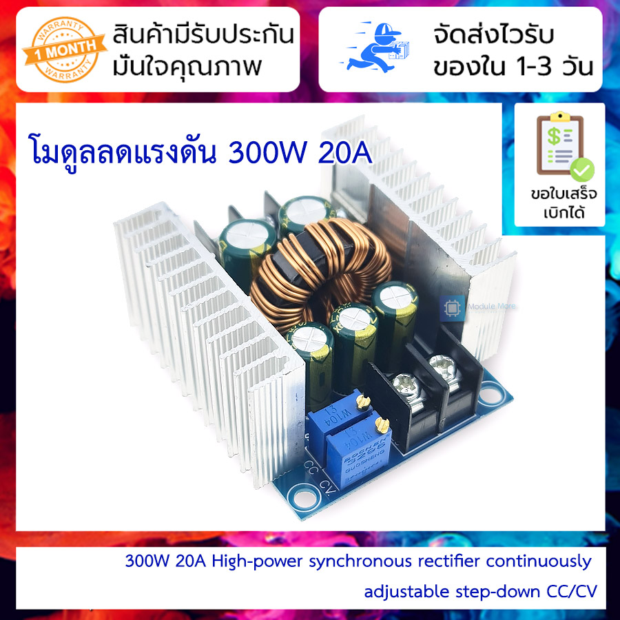     |
| เงื่อนไขอื่นๆ |
|
| Tags |
นโยบายการเปลี่ยนหรือคืนสินค้า
สินค้าทุกชิ้นมีการรับประกัน 30 วันครับ
โดยมีเงื่อนไขต่างๆดังนี้
1. ลูกค้าไม่ได้เป็นผู้ทำเสียหายเอง อาธิเช่น การต่อไฟเลี้ยงไม่ถูกต้อง (เซนเซอร์รับ 3.3v เราใส่ 5v อันนี้ไม่ได้เนอะ)
2. สินค้าต้องอยู่ในสภาพสมบูรณ์ ไม่แตกหักหรือเสียหายจากไฟ (เช่นไฟฟ้าลัดวงจรจนไฟไหม้)
3. ทางร้านไม่รับเปลี่ยนสินค้าจากความเข้าใจผิดของลูกค้าเอง เช่น ขนาดไม่ตรงกับงานที่ใช้, หรือซื้อไว้แต่ไม่ได้ใช้งาน เป็นต้น ลูกค้าสามารถสอบถามข้อมูลสินค้าหากมีความคลุมเครือก่อนสั่งซื้อได้ในไลน์ร้าน @modulemore ตลอดวันทำการ ยกเว้นเวลา 12.00-14.00 ที่อาจมีการตอบช้าในช่วงนี้
การส่งคืนสินค้า
การส่งคืนสินค้าจำเป็น ต้องมีใบเสร็จหรือสำเนา เพื่อความรวดเร็วในการตรวจสอบครับ
สามารถส่งคืนได้ผ่านที่อยู่ของร้าน คลิ๊ก โดยเขียนเป็นลายลักษณ์อักษรกำกับดังนี้
1. รายละเอียดรายการเสียหาย
2. ลูกค้าได้ทดสอบอะไรไปบ้าง
ทางร้านขอสงวนสิทธิ์ในการตัดสินใจเปลี่ยนสินค้าหรือคืนเงินครับ
ไทย▾


MEMBER ZONE

JOIN US
ร้านโมดูลมอร์
/www.modulemore.com/
สมัครสมาชิกร้านนี้ เพื่อรับสิทธิพิเศษ


Special thanks very good images from Freepik
ไทย▾
Choose your language
Language
Currency
Change
เปลี่ยนภาษา
▲
▼
รายการสั่งซื้อของฉัน
รายการสั่งซื้อของฉัน
ข้อมูลร้านค้านี้

โมดูลมอร์
ขาย arduino, diy, เรียน arduino, ทำหุ่นยนต์, ฝึกเขียนโปรแกรม, ตั้งแต่ระดับเริ่มต้นจนชำนาญ
เบอร์โทร : 0831710868
อีเมล : modulemore@gmail.com
อีเมล : modulemore@gmail.com
ส่งข้อความติดต่อร้าน
เกี่ยวกับร้านค้านี้
ค้นหาสินค้าในร้านนี้
ค้นหาสินค้า
สินค้าที่ดูล่าสุด
บันทึกเป็นร้านโปรด
Join เป็นสมาชิกร้าน
แชร์หน้านี้
แชร์หน้านี้
↑
TOP เลื่อนขึ้นบนสุด
TOP เลื่อนขึ้นบนสุด
สินค้าในตะกร้า ({{total_num}} รายการ)

ขออภัย ขณะนี้ยังไม่มีสินค้าในตะกร้า
ราคาสินค้าทั้งหมด
฿ {{price_format(total_price)}}
- ฿ {{price_format(discount.price)}}
ราคาสินค้าทั้งหมด
{{total_quantity}} ชิ้น
฿ {{price_format(after_product_price)}}
ราคาไม่รวมค่าจัดส่ง
รวมภาษีมูลค่าเพิ่มแล้ว
➜ เลือกซื้อสินค้าเพิ่ม