

รายละเอียดสินค้า
| ข้อมูล |
น้ำหนัก
บาร์โค้ด
ลงสินค้า
อัพเดทล่าสุด
|
| รายละเอียดสินค้า |
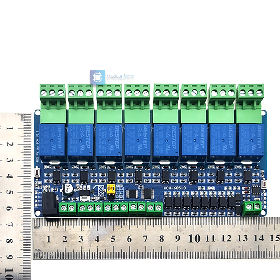
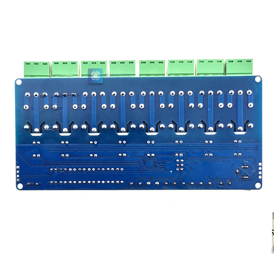
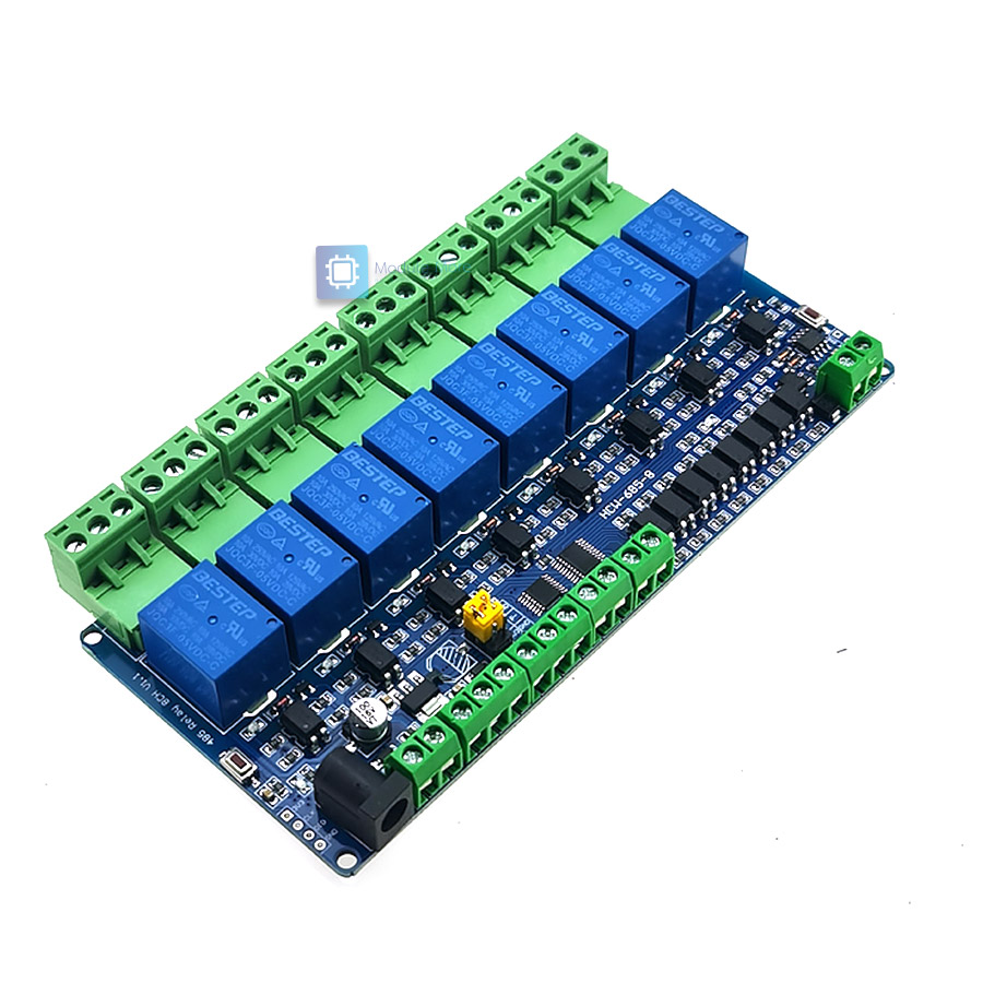
Product Introduction 8-channel Modbus relay moduleThe 8-channel Modbus relay module is equipped with a mature and stable 8-bit MCU and RS485 level communication chip. Using standard MODBUS RTU format RS485 communication protocol, it can realize 8 input signal detection and 8 relay output, which can be used for digital quantity detection or power control occasions. Product parameter 1. Onboard mature and stable STM8S103K3T6 MCU and MAX485 level conversion chip 2. Communication protocol: support standard Modbus RTU protocol 3. Communication interface: TTL UART interface supporting RS485/5V level 4. Communication baud rate: 4800/9600/19200, default 9600bps, support power-off save 5. Optocoupler input signal range: DC3.3-30V (this input cannot be used for relay control) 6. Output signal: relay switch signal, support manual, flash word, flash mode, flash off/flash The base number of the interruption delay is 0.1S, and the maximum flash word/flash time can be set to OxFFFF*0.1S=6553.5S 7. Device address: range 1-255, default 255, support power-off save 8. Baud rate, input signal, relay status, device address can be read by software/command 9. There are 8 5V, 10A/250V AC 10A/30V DC relays onboard, which can be continuously closed for 10 times, with diode effusion protection, and short response time 10. On-board relay switch indicator 11. Reserve the STM8 SWIM program programming port to support customers' secondary development and download their own firmware 12. Power supply voltage: DC7-30V, using 5.08mm terminal power supply Package Include: 1pc x 8-channel relay moduleModbus RTU Command Suppose the device address is 0xFF so return 00 10 00 00 00 01 02 00 FF EB 80 and the 9th btye is the devices address.
Turn OFF CH_1 Relay(Normal Mode)
Turn ON All relays
Turn OFF All relays
Set device address to 0x01
Set device address to 0xFF
Read device address
Read relay status
Read optocoupler input staturs
Set baud rate 4800bps
Set baud rate 9600bps
Set baud rate 19200bps
Turn ON CH_1 Relay(2S Flashing Mode)
Turn OFF CH_1 Relay(3S Flashing Mode)
    |
| เงื่อนไขอื่นๆ |
|
| Tags |
นโยบายการเปลี่ยนหรือคืนสินค้า
สินค้าทุกชิ้นมีการรับประกัน 30 วันครับ
โดยมีเงื่อนไขต่างๆดังนี้
1. ลูกค้าไม่ได้เป็นผู้ทำเสียหายเอง อาธิเช่น การต่อไฟเลี้ยงไม่ถูกต้อง (เซนเซอร์รับ 3.3v เราใส่ 5v อันนี้ไม่ได้เนอะ)
2. สินค้าต้องอยู่ในสภาพสมบูรณ์ ไม่แตกหักหรือเสียหายจากไฟ (เช่นไฟฟ้าลัดวงจรจนไฟไหม้)
3. ทางร้านไม่รับเปลี่ยนสินค้าจากความเข้าใจผิดของลูกค้าเอง เช่น ขนาดไม่ตรงกับงานที่ใช้, หรือซื้อไว้แต่ไม่ได้ใช้งาน เป็นต้น ลูกค้าสามารถสอบถามข้อมูลสินค้าหากมีความคลุมเครือก่อนสั่งซื้อได้ในไลน์ร้าน @modulemore ตลอดวันทำการ ยกเว้นเวลา 12.00-14.00 ที่อาจมีการตอบช้าในช่วงนี้
การส่งคืนสินค้า
การส่งคืนสินค้าจำเป็น ต้องมีใบเสร็จหรือสำเนา เพื่อความรวดเร็วในการตรวจสอบครับ
สามารถส่งคืนได้ผ่านที่อยู่ของร้าน คลิ๊ก โดยเขียนเป็นลายลักษณ์อักษรกำกับดังนี้
1. รายละเอียดรายการเสียหาย
2. ลูกค้าได้ทดสอบอะไรไปบ้าง
ทางร้านขอสงวนสิทธิ์ในการตัดสินใจเปลี่ยนสินค้าหรือคืนเงินครับ
ไทย▾


MEMBER ZONE

JOIN US
ร้านโมดูลมอร์
/www.modulemore.com/
สมัครสมาชิกร้านนี้ เพื่อรับสิทธิพิเศษ


Special thanks very good images from Freepik
ไทย▾
Choose your language
Language
Currency
Change
เปลี่ยนภาษา
▲
▼
รายการสั่งซื้อของฉัน
รายการสั่งซื้อของฉัน
ข้อมูลร้านค้านี้

โมดูลมอร์
ขาย arduino, diy, เรียน arduino, ทำหุ่นยนต์, ฝึกเขียนโปรแกรม, ตั้งแต่ระดับเริ่มต้นจนชำนาญ
เบอร์โทร : 0831710868
อีเมล : modulemore@gmail.com
อีเมล : modulemore@gmail.com
ส่งข้อความติดต่อร้าน
เกี่ยวกับร้านค้านี้
ค้นหาสินค้าในร้านนี้
ค้นหาสินค้า
สินค้าที่ดูล่าสุด
บันทึกเป็นร้านโปรด
Join เป็นสมาชิกร้าน
แชร์หน้านี้
แชร์หน้านี้
↑
TOP เลื่อนขึ้นบนสุด
TOP เลื่อนขึ้นบนสุด
สินค้าในตะกร้า ({{total_num}} รายการ)

ขออภัย ขณะนี้ยังไม่มีสินค้าในตะกร้า
ราคาสินค้าทั้งหมด
฿ {{price_format(total_price)}}
- ฿ {{price_format(discount.price)}}
ราคาสินค้าทั้งหมด
{{total_quantity}} ชิ้น
฿ {{price_format(after_product_price)}}
ราคาไม่รวมค่าจัดส่ง
รวมภาษีมูลค่าเพิ่มแล้ว
➜ เลือกซื้อสินค้าเพิ่ม