

Item description
| Information |
Item weight
Barcode
Created time
Last updated on
|
| Item description |
DESCRIPTION
The TXS0108E 8-Ch Logic Level Converter Module is a bi-directional device for converting signals between 3.3V and 5V logic systems.
KEY FEATURES OF TXS0108E 8-CH LOGIC LEVEL CONVERTER MODULE:
8 channels can convert up to 8 logic signals
Converts voltage levels between 1.2 to 3.6V and 1.65 to 5.5V systems
Bi-directional with automatic direction control
Each channel operates independently
Optimized for open-drain applications like I2C, but can also work in push-pull applications
Output enable allows outputs to be disabled
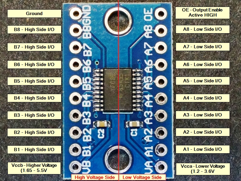
This module is typically used to connect 3.3V and 5V logic signals together, but it is compatible with many different logic voltages. The low (A) side can handle 1.2 to 3.6V logic levels. The high (B) side can handle 1.65 to 5.5V logic levels.
There are 8 bi-directional channels which is especially useful for buses that pass data in both directions. It can also be used for unidirectional signals like SPI.
The TXS0108 is designed for open-drain applications like I2C and includes dynamic pull-up / pull-down resistors, but it can be used in standard CMOS push-pull translation as well.
The output enable (OE) can be tied to Vcca to enable the outputs at all times. If it is desirable to have the device power up with the outputs disabled, use a pull-down resistor to ground which keeps the outputs off until it is enabled by driving the pin HIGH under MCU control. Disabling the OE is also useful for ultra low power applications since it shuts off the pull-up resistors and drops the idle current to a few uA.
When hooking up power, the lower voltage side must be connected to the ‘A’ side. This will typically be 3.3V. The higher voltage side which is typically 5V should be connected to the ‘B’ side.
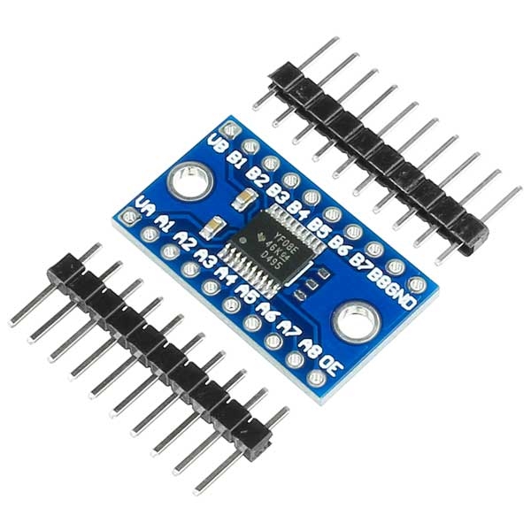
The device is not affected by power supply sequencing during power up, so having one side powered and the other side unpowered will not damage the device. 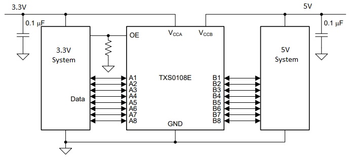 Module OperationTo use the module, you hook up the two voltages that you want to convert between to the A (low Voltage) and B (High Voltage) inputs. The higher voltage is always connected to the B side. If using with an Arduino to interface to a 3.3V module, you would typically connect the 3.3V output of the Arduino to the Low Voltage Vcca input and the 5V output of the Arduino to the High Voltage Vccb input. The ground connection should be common with the ground of both logic systems. You then hook-up the lower voltage logic signals to the A1-A8 pins and the higher voltage logic signals to the corresponding B1-B8 pins (A1 connects to B1, etc) and you are set to go. There is no direction control required for the bi-directional functionality. The OE pin needs to be pulled to Vcca if the outputs will always be enabled. Add a pull down resistor of 1K or so if you want the device to come up disabled until the uC enables it by driving the pin HIGH. The module comes with 2 strips of male headers. These can be soldered on for use on a breadboard, or you can attach wires directly to the board depending on what your application requires. If soldering the headers on, it is recommended to insert the headers into a solderless breadboard first to hold them in alignment while soldering. Module ConnectionsThe board has the following I/O connections:
  |
| Conditions |
|
| Tags |
Exchange or return policy
Every item comes with a 30-day warranty. However, there are certain conditions that apply:
-
The customer should not be responsible for any self-inflicted damage, such as incorrect power connections (for example, supplying 5V instead of the required 3.3V for a sensor).
-
The product must be in perfect condition, without any breakage or damage caused by electricity (e.g., short circuits leading to electrical fires).
-
The store does not accept product exchanges due to customer misunderstandings, such as purchasing the wrong size for their project or buying something without eventually using it. Customers can inquire about the product details and ensure compatibility before making a purchase by contacting us through our Line account @modulemore during business hours. Please note that there may be delays in response between 12:00 PM and 2:00 PM.
Return Policy: To initiate a product return, customers must provide the original receipt or a copy for quick verification. Returns can be sent to our store address by following these guidelines:
- Provide a detailed description of the damaged item(s).
- Mention any tests or experiments conducted by the customer.
Please note that the store reserves the right to make the final decision regarding product replacement or refund.
English▾


MEMBER ZONE

JOIN US
ร้านModuleMore
/www.modulemore.com/en
Become a member of this store to receive special offers and promotions
 ModuleMore
Become a member of this store to receive special offers and promotions


Special thanks very good images from Freepik
English▾
Choose your language
Language
Currency
Change
Modify language
▲
▼
My orders
My orders
This seller's information

ModuleMore
Arduino compatible board, Iot, ESP32, ESP8266, Nodemcu, Raspberry pi, micro:bit and etc.
Mobile number : 0831710868
E-mail : paheyisoicus@gmail.com
E-mail : paheyisoicus@gmail.com
Send message to seller
About this seller
Search items from this seller
Search for items
Recently viewed items
Favourite this seller
Join as a Member
Share this page
Share this page
↑
TOP Back to top
TOP Back to top
Items in cart ({{total_num}} type)

We apologise, your cart currently is empty
Total
฿ {{price_format(total_price)}}
- ฿ {{price_format(discount.price)}}
Total
{{total_quantity}} Unit(s)
฿ {{price_format(after_product_price)}}
excluding shipping fee
VAT Included.
➜ Continue shopping