

Item description
| Highlight |
Datasheet : PZEM-004T
https://innovatorsguru.com/wp-content/uploads/2019/06/PZEM-004T-V3.0-Datasheet-User-Manual.pdf
Datasheet : PZEM-014 / PZEM-016
https://images-na.ssl-images-amazon.com/images/I/81GtkIOyZaL.pdf
|
|||||||||||||||||||||||||||||||||||||||
| Information |
Item weight
Barcode
Created time
Last updated on
|
|||||||||||||||||||||||||||||||||||||||
| Item description |
AC communication module Overview This document describes the specification of the PZEM-004T AC communication module, the module is mainly used for measuring AC voltage, current, active power, frequency, power factor and active energy, the module is without display function, the data is read through the TTL interface. PZEM-004T-100A: Measuring Range 100A (external transformer) 1.Function descriptionVoltage
Measuring range:80~260V
Resolution: 0.1V
Measurement accuracy: 0.5%
Current
Measuring range:0~10A(PZEM-004T-10A); 0~100A(PZEM-004T-100A)
Starting measure current: 0.01A(PZEM-004T-10A); 0.02A(PZEM-004T-100A)
Resolution: 0.001A
Measurement accuracy: 0.5%
Active power
Measuring range:0~3kW(PZEM-004T-10A); 0~23kW(PZEM-004T-100A)
Starting measure power: 0.4W
Resolution: 0.1W
Display format:
<1000W, it display one decimal, such as: 999.9W ≥1000W, it display only integer, such as: 1000W Measurement accuracy: 0.5%
Power factor
Measuring range:0.00~00
Resolution: 01
Measurement accuracy: 1%
Frequency
Measuring range:45Hz~65Hz
Resolution: 0.1Hz
Measurement accuracy: 0.5%
Active energy
Measuring range: 0~99kWh
Resolution: 1Wh
Measurement accuracy: 0.5%
Display format:
<10kWh, the display unit is Wh(1kWh=1000Wh), such as: 9999Wh ≥10kWh, the display unit is kWh, such as: 9999.99kWh Reset energy: use software to reset.
Over power alarm
Active power threshold can be set, when the measured active power exceeds the threshold, it can alarm Communication interface
RS485 interface。
2 Communication protocolPhysical layer protocol
Physical layer use UART to RS485 communication interface Baud rate is 9600, 8 data bits, 1 stop bit, no parity Application layer protocol
The application layer use the Modbus-RTU protocol to communicate. At present, it only supports function codes such as 0x03 (Read Holding Register), 0x04 (Read Input Register), 0x06 (Write Single Register), 0x41 (Calibration), 0x42 (Reset energy).etc. 0x41 function code is only for internal use (address can be only 0xF8), used for factory calibration and return to factory maintenance occasions, after the function code to increase 16-bit password, the default password is 0x3721 The address range of the slave is 0x01 ~ 0xF7. The address 0x00 is used as the broadcast address, the slave does not need to reply the master. The address 0xF8 is used as the general address, this address can be only used in single-slave environment and can be used for calibration etc.operation. Read the measurement result
The command format of the master reads the measurement result is(total of 8 bytes): Slave Address + 0x04 + Register Address High Byte + Register Address Low Byte + Number of Registers High Byte + Number of Registers Low Byte + CRC Check High Byte + CRC Check Low Byte. The command format of the reply from the slave is divided into two kinds: Correct Reply: Slave Address + 0x04 + Number of Bytes + Register 1 Data High Byte + Register 1 Data Low Byte + ... + CRC Check High Byte + CRC Check Low Byte Error Reply: Slave address + 0x84 + Abnormal code + CRC check high byte + CRC check low byte Abnormal code analyzed as following (the same below) 0x01,Illegal function
0x02,Illegal address
0x03,Illegal data
0x04,Slave error
The register of the measurement results is arranged as the following table
For example, the master sends the following command (CRC check code is replaced by 0xHH and 0xLL, the same below) 0x01 + 0x04 + 0x00 + 0x00 + 0x00 + 0x0A + 0xHH + 0xLL Indicates that the master needs to read 10 registers with slave address 0x01 and the start address of the register is 0x0000 The correct reply from the slave is as following: 0x01 + 0x04 + 0x14 + 0x08 + 0x98 + 0x03 + 0xE8+0x00 + 0x00 +0x08 + 0x98+ 0x00 + 0x00 + 0x00 + 0x00 + 0x00 + 0x00 + 0x01 + 0xF4 + 0x00 + 0x64 + 0x00 + 0x00 + 0xHH + 0xLL The above data shows Voltageis 0x0898, converted to decimal is 2200, display0V
Current is0x000003E8, converted to decimal is 1000, display 000A
Power is 0x00000898,converted to decimal is 2200, display 220.0W
Energy is 0x00000000,converted to decimal is 0, display 0Wh
Frequency is 0x01F4,converted to decimal is 500, display 50.0Hz
Power factor is 0x0064,converted to decimal is 100, display 1.00
Alarm status is 0x0000, indicates that the current power is lower than the alarm power threshold
Read and modify the slave parameters
At present,it only supports reading and modifying slave address and power alarm threshold The register is arranged as the following table
The command format of the master to read the slave parameters and read the measurement results are same(descrybed in details in Section 2.3), only need to change the function code from 0x04 to 0x03. The command format of the master to modify the slave parameters is (total of 8 bytes): Slave Address + 0x06 + Register Address High Byte + Register Address Low Byte + Register Value High Byte + Register Value Low Byte + CRC Check High Byte + CRC Check Low Byte. The command format of the reply from the slave is divided into two kinds: Correct Response: Slave Address + 0x06 + Number of Bytes + Register Address Low Byte + Register Value High Byte + Register Value Low Byte + CRC Check High Byte + CRC Check Low Byte. Error Reply: Slave address + 0x86 + Abnormal code + CRC check high byte + CRC check low byte. For example, the master sets the slave's power alarm threshold: 0x01 + 0x06 + 0x00 + 0x01 + 0x08 + 0xFC + 0xHH + 0xLL Indicates that the master needs to set the 0x0001 register (power alarm threshold) to 0x08FC (2300W). Set up correctly, the slave return to the data which is sent from the master. For example, the master sets the address of the slave 0x01 + 0x06 + 0x00 + 0x02 + 0x00 + 0x05 + 0xHH + 0xLL Indicates that the master needs to set the 0x0002 register (Modbus-RTU address) to 0x0005 Set up correctly, the slave return to the data which is sent from the master. Reset energy
The command format of the master to reset the slave's energy is (total 4 bytes): Slave address + 0x42 + CRC check high byte + CRC check low byte. Correct reply: slave address + 0x42 + CRC check high byte + CRC check low byte. Error Reply: Slave address + 0xC2 + Abnormal code + CRC check high byte + CRC check low byte Calibration
The command format of the master to calibrate the slave is (total 6 bytes): 0xF8 + 0x41 + 0x37 + 0x21 + CRC check high byte + CRC check low byte. Correct reply: 0xF8 + 0x41 + 0x37 + 0x21 + CRC check high byte + CRC check low byte. Error Reply: 0xF8 + 0xC1 + Abnormal code + CRC check high byte + CRC check low byte. It should be noted that the calibration takes 3 to 4 seconds, after the master sends the command, if the calibration is successful, it will take 3 ~ 4 seconds to receive the response from the slave. CRC check
CRC check use 16bits format, occupy two bytes, the generator polynomial is X16 + X15 + X2 +1, the polynomial value used for calculation is 0xA001. The value of the CRC check is a frame data divide all results of checking all the bytes except the CRC check value.
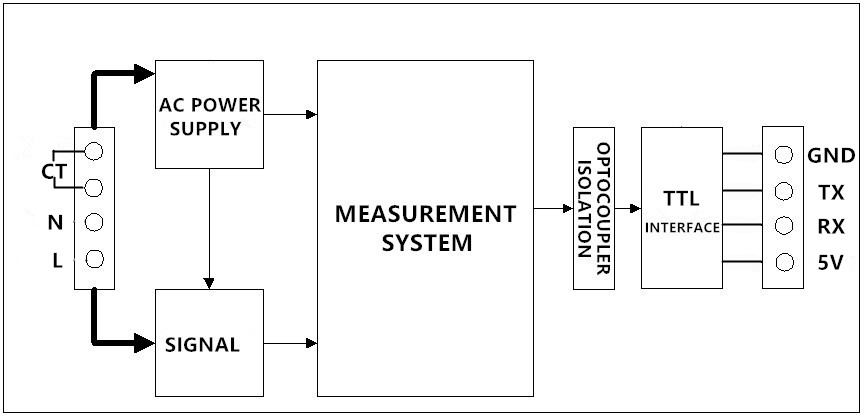
3 Functional block diagram Picture 3.1 PZEM-004T-10A Functional block diagram  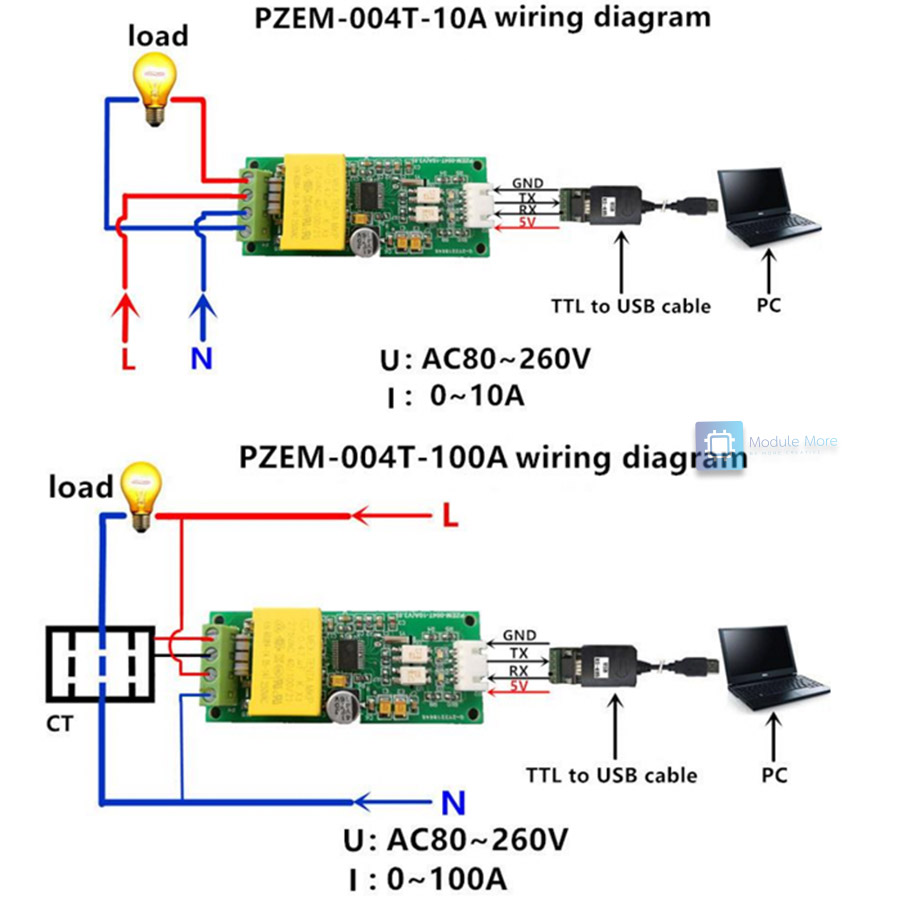  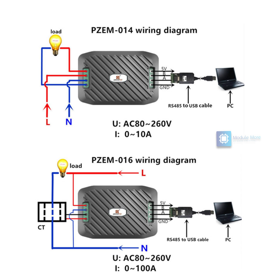 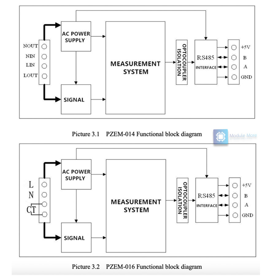 |
|||||||||||||||||||||||||||||||||||||||
| Conditions |
|
|||||||||||||||||||||||||||||||||||||||
| Tags |
Exchange or return policy
Every item comes with a 30-day warranty. However, there are certain conditions that apply:
-
The customer should not be responsible for any self-inflicted damage, such as incorrect power connections (for example, supplying 5V instead of the required 3.3V for a sensor).
-
The product must be in perfect condition, without any breakage or damage caused by electricity (e.g., short circuits leading to electrical fires).
-
The store does not accept product exchanges due to customer misunderstandings, such as purchasing the wrong size for their project or buying something without eventually using it. Customers can inquire about the product details and ensure compatibility before making a purchase by contacting us through our Line account @modulemore during business hours. Please note that there may be delays in response between 12:00 PM and 2:00 PM.
Return Policy: To initiate a product return, customers must provide the original receipt or a copy for quick verification. Returns can be sent to our store address by following these guidelines:
- Provide a detailed description of the damaged item(s).
- Mention any tests or experiments conducted by the customer.
Please note that the store reserves the right to make the final decision regarding product replacement or refund.
English▾


MEMBER ZONE

JOIN US
ร้านModuleMore
/www.modulemore.com/en
Become a member of this store to receive special offers and promotions
 ModuleMore
Become a member of this store to receive special offers and promotions


Special thanks very good images from Freepik
English▾
Choose your language
Language
Currency
Change
Modify language
▲
▼
My orders
My orders
This seller's information

ModuleMore
Arduino compatible board, Iot, ESP32, ESP8266, Nodemcu, Raspberry pi, micro:bit and etc.
Mobile number : 0831710868
E-mail : paheyisoicus@gmail.com
E-mail : paheyisoicus@gmail.com
Send message to seller
About this seller
Search items from this seller
Search for items
Recently viewed items
Favourite this seller
Join as a Member
Share this page
Share this page
↑
TOP Back to top
TOP Back to top
Items in cart ({{total_num}} type)

We apologise, your cart currently is empty
Total
฿ {{price_format(total_price)}}
- ฿ {{price_format(discount.price)}}
Total
{{total_quantity}} Unit(s)
฿ {{price_format(after_product_price)}}
excluding shipping fee
VAT Included.
➜ Continue shopping