

Item description
| Information |
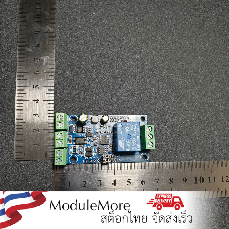
Item weight
Barcode
Created time
Last updated on
|
| Item description |
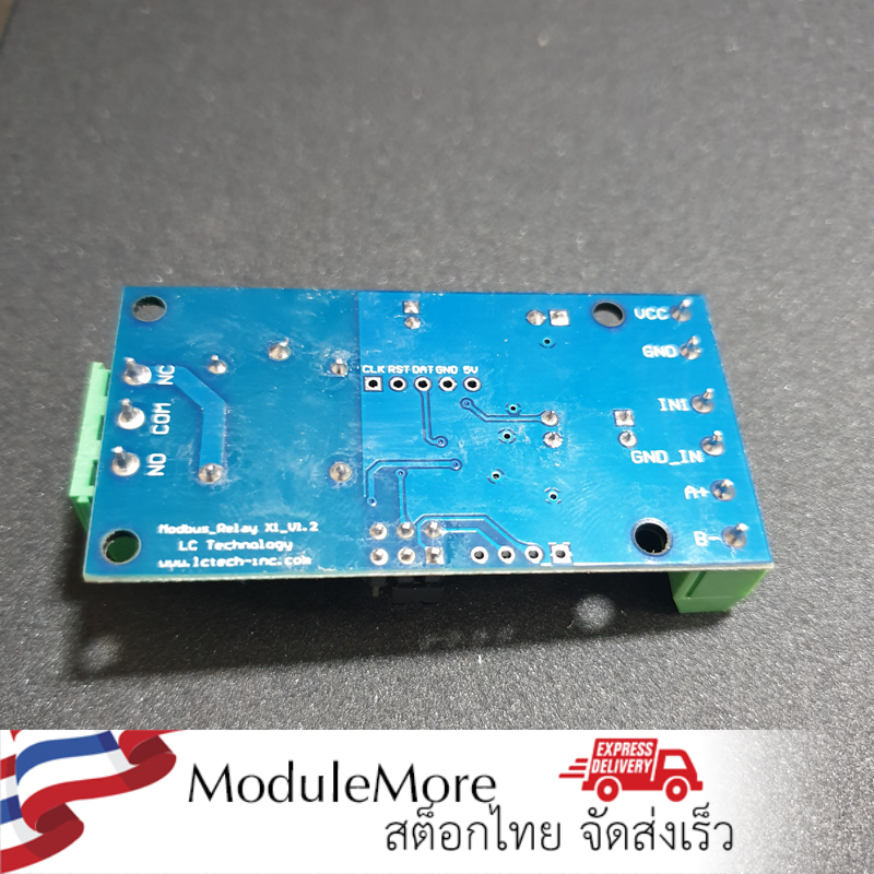
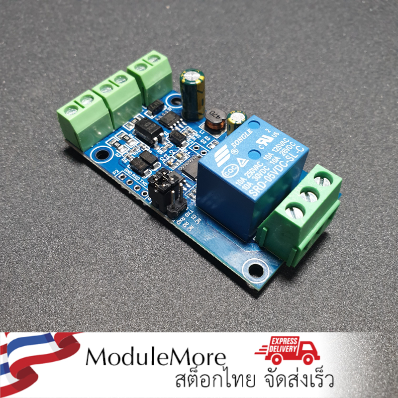
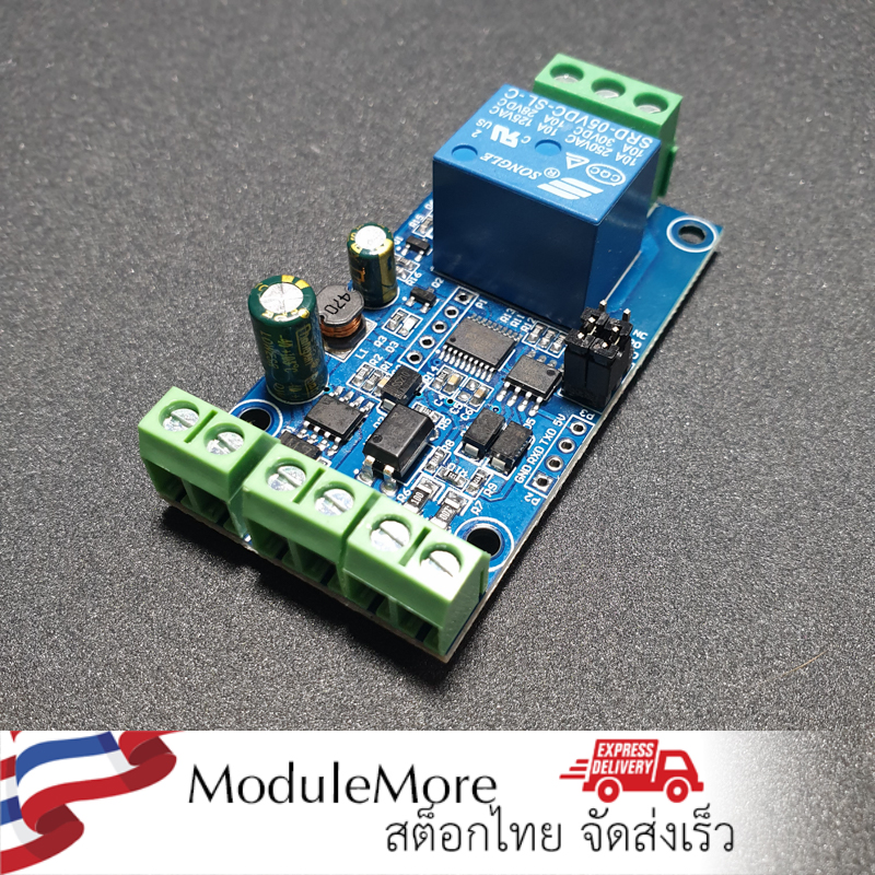
วิธีการใช้งาน 1.Overview Functions:  Arduino Libraryhttps://robokits.co.in/downloads/Modbus%20Relay.zip
Modbus RTU CommandSuppose the device address is 0xFF so return 00 10 00 00 00 01 02 00 FF EB 80 and the 9th btye is the devices address.
Turn OFF CH_1 Relay(Normal Mode)
Turn ON All relays
Turn OFF All relays
Set device address to 0x01
Set device address to 0xFF
Read device address
Read relay status
Read optocoupler input staturs
Set baud rate 4800bps
Set baud rate 9600bps
Set baud rate 19200bps
Turn ON CH_1 Relay(2S Flashing Mode)
Turn OFF CH_1 Relay(3S Flashing Mode)
       |
| Conditions |
1,VCC,GND:DC7-24V power input 3. Modbus RTU introduction of instruction Modbus device through receive from external control terminal (like Host computer/MCU )Modbus RTU instruction to perform related operations, one frame instruction generally consists of device address, function code, register address, register data, and check code,frame length is related to function code. Each frame date’s first byte is the device address.can set range on 1-255 default 255(scilicet 0xFF),the last 2byte is CRC check code. 1, open no.1 relay (manual mode) 2, turn off the relay No. 1 (manual mode) 5, set the device address to 1 6. Set the device address to 255 7, read device address 8,read relay state 9,Read optocoupler input status 10.Set the baud rate to 4800 Send:FF 03 03 E8 00 01 11 A4 14, turn on no.1 relay (flash ON mode) 15, turn on no.1 relay (flash OFF mode) |
| Tags |
Exchange or return policy
Every item comes with a 30-day warranty. However, there are certain conditions that apply:
-
The customer should not be responsible for any self-inflicted damage, such as incorrect power connections (for example, supplying 5V instead of the required 3.3V for a sensor).
-
The product must be in perfect condition, without any breakage or damage caused by electricity (e.g., short circuits leading to electrical fires).
-
The store does not accept product exchanges due to customer misunderstandings, such as purchasing the wrong size for their project or buying something without eventually using it. Customers can inquire about the product details and ensure compatibility before making a purchase by contacting us through our Line account @modulemore during business hours. Please note that there may be delays in response between 12:00 PM and 2:00 PM.
Return Policy: To initiate a product return, customers must provide the original receipt or a copy for quick verification. Returns can be sent to our store address by following these guidelines:
- Provide a detailed description of the damaged item(s).
- Mention any tests or experiments conducted by the customer.
Please note that the store reserves the right to make the final decision regarding product replacement or refund.
English▾


MEMBER ZONE

JOIN US
ร้านModuleMore
/www.modulemore.com/en
Become a member of this store to receive special offers and promotions
 ModuleMore
Become a member of this store to receive special offers and promotions


Special thanks very good images from Freepik
English▾
Choose your language
Language
Currency
Change
Modify language
▲
▼
My orders
My orders
This seller's information

ModuleMore
Arduino compatible board, Iot, ESP32, ESP8266, Nodemcu, Raspberry pi, micro:bit and etc.
Mobile number : 0831710868
E-mail : paheyisoicus@gmail.com
E-mail : paheyisoicus@gmail.com
Send message to seller
About this seller
Search items from this seller
Search for items
Recently viewed items
Favourite this seller
Join as a Member
Share this page
Share this page
↑
TOP Back to top
TOP Back to top
Items in cart ({{total_num}} type)

We apologise, your cart currently is empty
Total
฿ {{price_format(total_price)}}
- ฿ {{price_format(discount.price)}}
Total
{{total_quantity}} Unit(s)
฿ {{price_format(after_product_price)}}
excluding shipping fee
VAT Included.
➜ Continue shopping